Activity B.3. True 3D models
In addition to the 2D basic shapes we saw back in Activity A, OpenSCAD has 3D primitives like cube and cylinder that work similarly, but are of course three-dimensional. The basic 3D shapes are the cube, cylinder, sphere, and polyhedron. Each one is pretty similar to the related two-dimensional shape.
Steps:
All the activities here assume that OpenSCAD is open and working, and that you have launched it with the usual graphical user interface.
- Go to the File menu, and select New File.
- Navigate to the Editor window.
- In the Editor window type the code to create an object (code given in examples that follow)
- In the main Menu bar along the top, select Save and give the model an appropriate name ending in .scad, like extrusion.scad.
Rendering and Exporting a 3D Printable File
The file ending in .scad can be edited in OpenSCAD going forward. (SVG files can be opened in OpenSCAD, but not edited.) Now that we have saved the file we can try rendering, exporting and printing it.
- To get a 3D print rather than a 2D tactile drawing, we need to export a different file. Go to the File menu and then Export and select Export to STL. STL files are what a 3D printer requires.
- For more on 3D printing, see the "3D Printing" section in the Introduction of this guide.
- In “Advanced Features” at the end of this Activity, we discuss techniques for creating both 2D and 3D shapes, which you can find in detail in Activity A.1 and B.2, respectively.
Basic 3D Shapes
To make a rectangular solid, we use the cube() function. Similar to the square() function, it is called a “cube” but can have unequal sides, and be centered around the origin or not. For example
cube([5, 7, 10]);
will be a rectangular solid 5 mm long in the x-dimension, 7 mm in y, and 10 high in the z dimension. 3D shapes can be combined the same way as 2D ones (with union(), difference(), and intersection()) and can be scaled, rotated and so on (but all three axes need to be specified). Creating a cylinder is similar:
cylinder(h = 5, r = 10);
Will create a cylinder of radius 10 mm and height 5 mm. However, there is also a special case of a cylinder that creates a cone:
cylinder(h= 5, r1 = 10, r2 = 0);
This creates a short, fat cone 5 mm high, 10 mm radius at the base, and a point on top. The two radii represent the base and top of the cone. The top is pointy, and thus has a radius of zero.
OpenSCAD's polyhedron module is a bit more complicated with more to think about, with potential pitfalls described on the manual page.
By rotating and translating these shapes in three dimensions, you can quickly build up 3D objects.
Tip: Simple to Complex
Remind students that 3D coding is still all about shapes and structure. Just like in 2D, we build up from primitives, only now there’s an extra axis to think about. Start with code that creates one simple shape, then add complexity layer by layer.
3D House Example
The example that follows is a simple model of a house with a sloped roof, a cylindrical chimney, and an open doorway in the front. It is created with the following code:
difference() {
union() {
translate([-10, -10, 0]) cube(20);
translate([0, 0, 20]) rotate([90, 0, 0]) cylinder(r = 10, h = 20, center = true,
$fn = 4);
translate([7, 0, 0]) cylinder(r = 2, h = 28);
}
translate([-7, -15, -5]) cube([5, 10, 15]);
}

The initial cube creates the vertical walls of the house. The roof was then added as a cylinder that was rotated to have one end facing the front of the house, and translated to that the top of the initial cube runs exactly through its center. Setting $fn = 4 for this cylinder gives it a square profile, creating a 90-degree peak at the top of the roof. This shape also could have been produced using another cube, but it would have required a slightly more complicated rotation, and we would have needed a factor of the square root of 2 to calculate the correct dimensions.
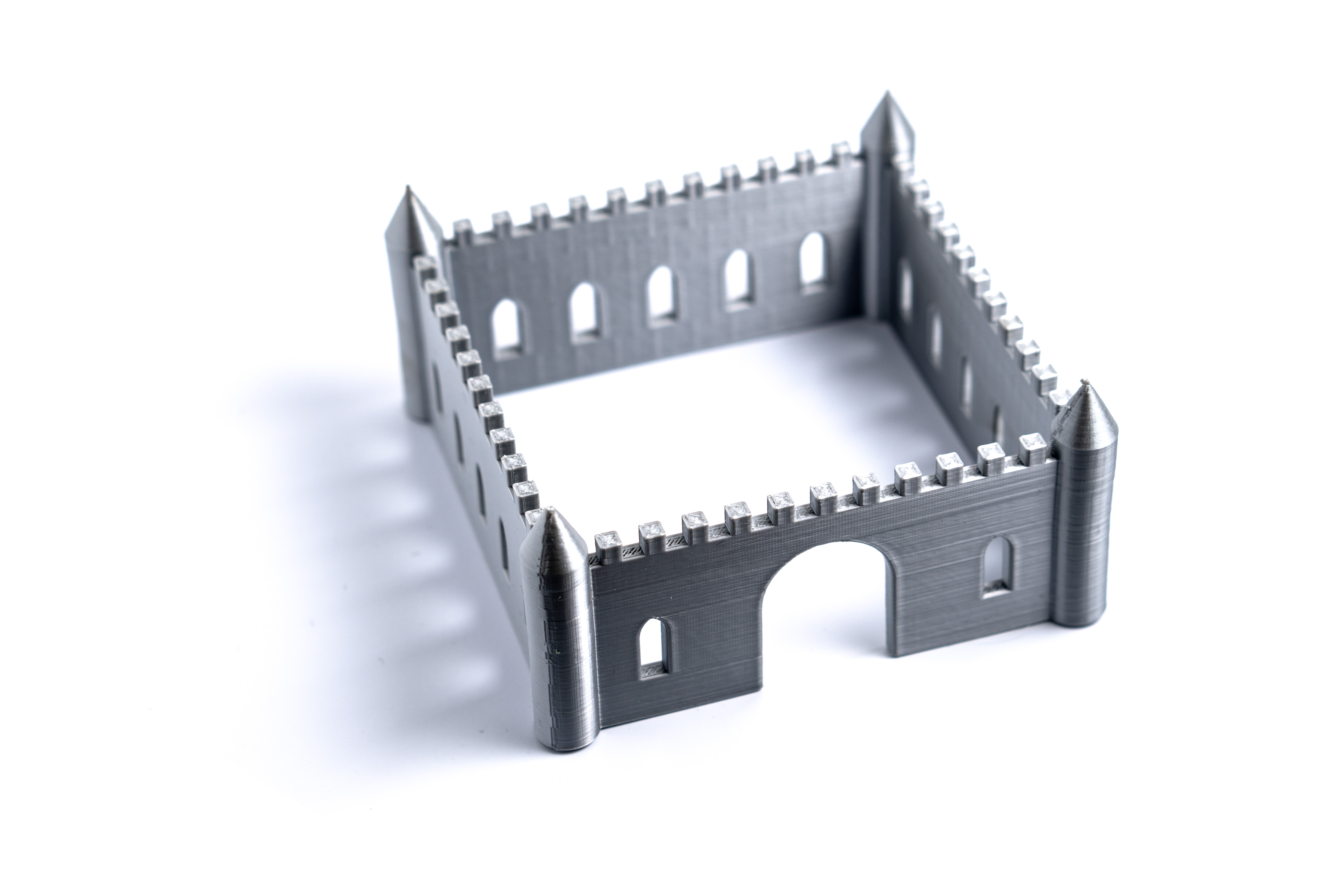
The chimney is a simple cylinder protruding through the roof. This cylinder is actually a heptagonal (7-sided) prism, due to letting OpenSCAD automatically choose the number of sides for this scale. Finally, we used a union to join all of these shapes together, and a difference to subtract a smaller cube from this unioned shape to create a doorway into our house. If you would like to try a more-complex example, in our Make: Geometry book we gradually build up a complex castle in OpenSCAD. The photo that follows is the final state, from Chapter 13.
Advanced Features: hull(), offset(), and minkowski() Modules
OpenSCAD's hull() module is used for creating a "convex hull" of one or more shapes. A convex hull is the smallest shape (2D or 3D, depending on the type of shapes inside) that surrounds a shape or shapes without any discontinuities between shapes, and with no concave (inward-facing) points. You can think of this like putting a layer of shrinkwrap around the shapes that wraps around them, as well as the space between them. For example, one quick way to create a shape with rounded corners in OpenSCAD is to place a circle at each corner, then wrap those circles in a hull() to fill in the space in between. This makes a (2D) square with rounded corners:
hull() {
translate([0, 0, 0]) circle(5);
translate([10, 0, 0]) circle(5);
translate([0, 10, 0]) circle(5);
translate([10, 10, 0]) circle(5);
}

A square with rounded corners, file hull.svg
The hull() module generally processes very quickly in 2D, but may take a bit longer when working in 3D, especially using spheres, because they can have so many more facets for OpenSCAD to calculate.
To make a more complex 2D shape with rounded corners, especially if it has concave sections that you want to preserve, the offset() module may be even more useful. An offset lets you push all of the edges of a shape outward. When you push the edges outward, any convex (outward-pointing) corners between them will become rounded, with a radius equal to the distance they were pushed out. If you use a negative value, the corners will be pushed inward, and concave corners will be rounded. However, any sections of that shape with a width of twice that distance or thinner will be lost.
Just doing a single offset will change the dimensions of a shape. However, you can easily add round corners to a 2D shape without otherwise affecting its dimensions by doing a negative offset, followed by a positive offset of the same amount. Likewise, you can round the concave corners by doing the same thing in the opposite order. If you want to do both, you can do it with a series of three offsets. Just make sure that the sum of all of the successive offsets equals zero to maintain your dimensions, and that there is no point along the way where the total offset is a negative value equal to half of your minimum width. This code makes a cross-shaped 2D object:
offset(5) offset(-15) offset(10) {
square([20, 80], center = true);
square([80, 20], center = true);
}

A cross shape with rounded edges, file offset.svg
A third way to round off corners in OpenSCAD is to use the minkowski() module. This is the simplest of the three methods to write, but the most computationally intensive to calculate. It works by taking one shape and "applying" it to another, such that you are essentially placing copies of one shape at each vertex of the other. While a minkowski() operation works in 3D, it can be extremely slow and memory-intensive (especially when using spheres with large facet counts, which is usually what you would want). Thus, people generally try to avoid using this operation in 3D. A 2D minkowski() operation requires much less processing, and usually will not require excessive amounts of processing time or memory. For example, this creates a 2D square with rounded corners:
minkowski() {
circle(5);
square(10);
}

A square with rounded corners, file minkowski.svg
Teaching Tip: Creating in 3D by Starting in 2D
Many of OpenSCAD's operations are faster in 2D than in 3D. Working in 2D also means that you do not need to write a height value (either as a number or a variable name) over and over for each primitive when building up a shape in which they will all be the same height. You only need to use this value once, when you extrude a 2D shape into 3D.
A less obvious advantage comes when you want to center things. When designing for 3D printing, it is often advantageous to design an object with all of its parts sitting flat on the print bed. In the OpenSCAD house example, for instance, the walls were created from a cube with the center of its bottom face at the origin. To do this, a 20 mm cube was translated by -10 mm in the x and y directions, but zero in z.
translate([-10, -10, 0]) cube(20);
This could also have been done by centering the cube, but then it would also have been centered in Z, so it would still need to be translated up to achieve the same results.
translate([0, 0, 10]) cube(20, center = true);
In either case, you need to know the dimensions of the cube to know how far to translate it, and if you were doing something more complex, you would use a variable for this.
height = 20;
translate([0, 0, height / 2]) cube([10, 30, height], center = true);
Cylinders do not have this problem, because centering a cylinder only centers it in the z dimension. It is already centered in x and y. However, when you create a rectangular solid by using linear_extrude() on a square, you can separately control whether it is centered in the x, y plane and the z axis. To get a 20 mm cube with the center of its bottom face at the origin, all we need is:
linear_extrude(20) square(20);
With experience, it will become clearer when this technique makes sense. Take a look at some of the models in the repositories we describe in Section C for examples.
Learning More
Programming of any sort is not easy. OpenSCAD is a little quirky relative to some languages, but it is a good way of learning geometrical concepts through a text interface. With practice, it is possible to create very complex models. In Section C we give a general review of the models created for the books Make: Geometry, Make: Trigonometry, and Make: Calculus and our two books of science projects, and how to find the various models.