Activity B. 2. Moving from 2D to 3D
Everything we have seen so far has been aimed at two dimensions, creating an output in SVG format for a 2D tactile drawing. Now, we will move on to 3D objects for a 3D printer. OpenSCAD has 3D shapes that correspond to the 2D one (for example, sphere versus circle) and we will get to those in the next Activity. The easiest transformation is to just extrude the shape into the third dimension.
OpenSCAD has two types of extrusion: linear_extrude() and rotate_extrude(). The linear_extrude function takes a 2D shape and, well, extrudes it into the third dimension by a specified thickness. Imagine you had a cookie cutter the shape of your original 2D shape: the extruded version would be the cookie.
Steps:
All the activities here assume that OpenSCAD is open and working, and that you have launched it with the usual graphical user interface.
- Go to the File menu, and select New File.
- Navigate to the Editor window.
- In the Editor window type the code to create an object (code given in examples that follow)
- In the main Menu bar along the top, select Save and give the model an appropriate name ending in .scad, like extrusion.scad.
Rendering and Exporting a 3D Printable File
The file ending in .scad can be edited in OpenSCAD going forward. (SVG files can be opened in OpenSCAD, but not edited.) Now that we have saved the file we can try rendering, exporting and printing it.
- To get a 3D print rather than a 2D tactile drawing, we need to export a different file. Go to the File menu and then Export and select Export to STL. STL files are what a 3D printer requires.
- For more on 3D printing, see the "3D Printing" section in the Introduction of this guide.
Teaching Tip: File Type
Always connect the change in file type to the change in purpose (.svg for tactile drawings and .stl for 3D printing). Have students talk through when and why you’d use each format, don’t assume the distinction is obvious.
Linear Extrusion
If we wanted to create a 3D printed L shape like we had in the previous Activity, we would use OpenSCAD code like this:
linear_extrude(height = 5, scale = 1.0) difference() {
square([45, 45]);
translate([15, 15]) square([30, 30]);
}
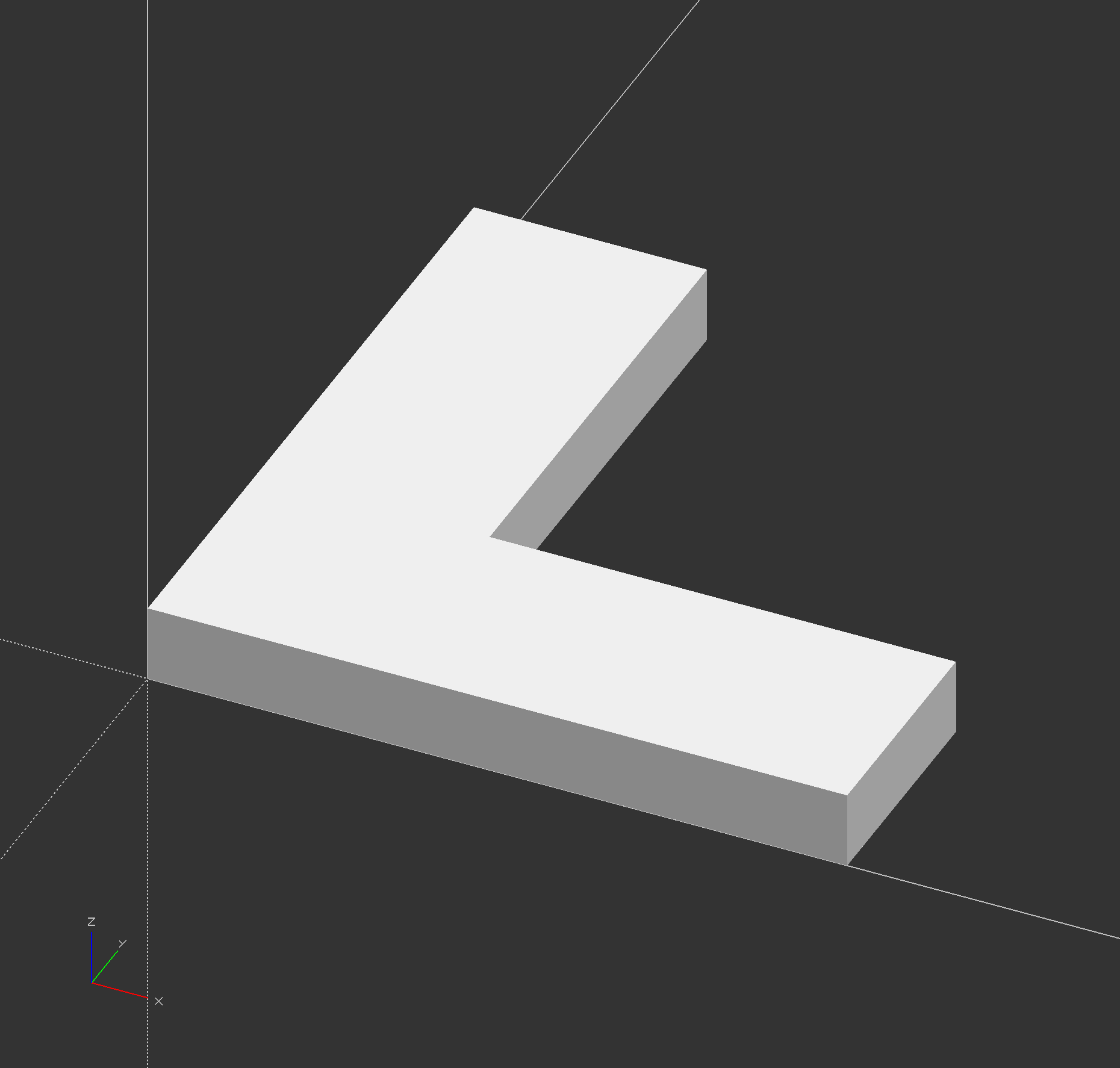
Note that we just add the linear_extrude function to the front of our model (enclosing what comes after it), as if it was a scale or translate function. The height parameter (which has to be called that, case sensitive) tells us that the resulting L will be 5 mm thick, and the scale parameter says that it will not get bigger or smaller as we extrude it. For example, if we make scale = 0.5,
linear_extrude(height = 5, scale = 0.5) difference() {
square([45, 45]);
translate([15, 15]) square([30, 30]);
}
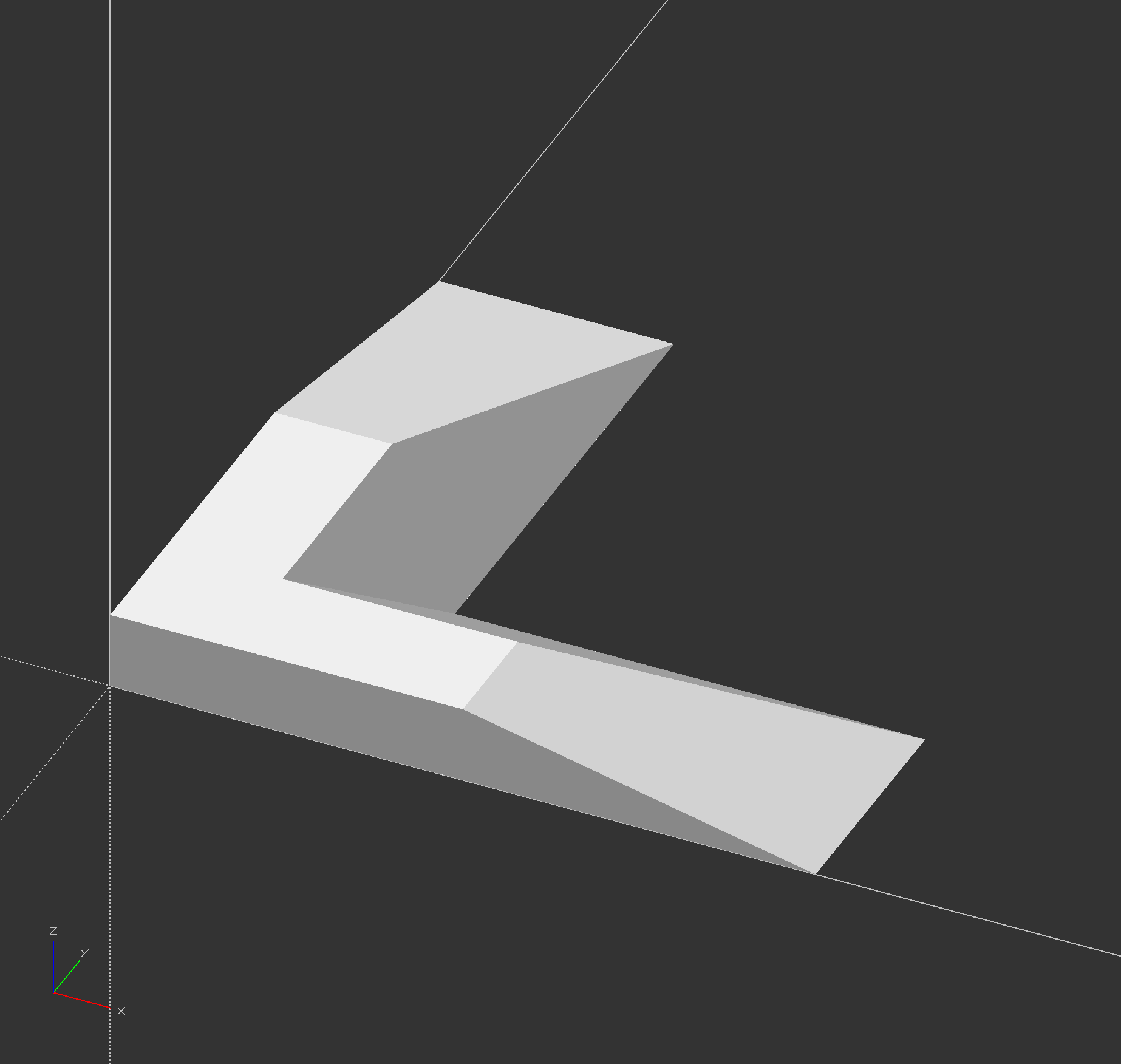
Now the L gets smaller as we go up in the z dimension. (You can omit the scale parameter if it equals 1, which is the default, but we used it here to make the point.) The linear_extrude function has fancier parameters as well which you can explore, but this capability should be enough for now. If you are extruding in other than the z direction you may need to add other parameters.
Rotating Extrusion
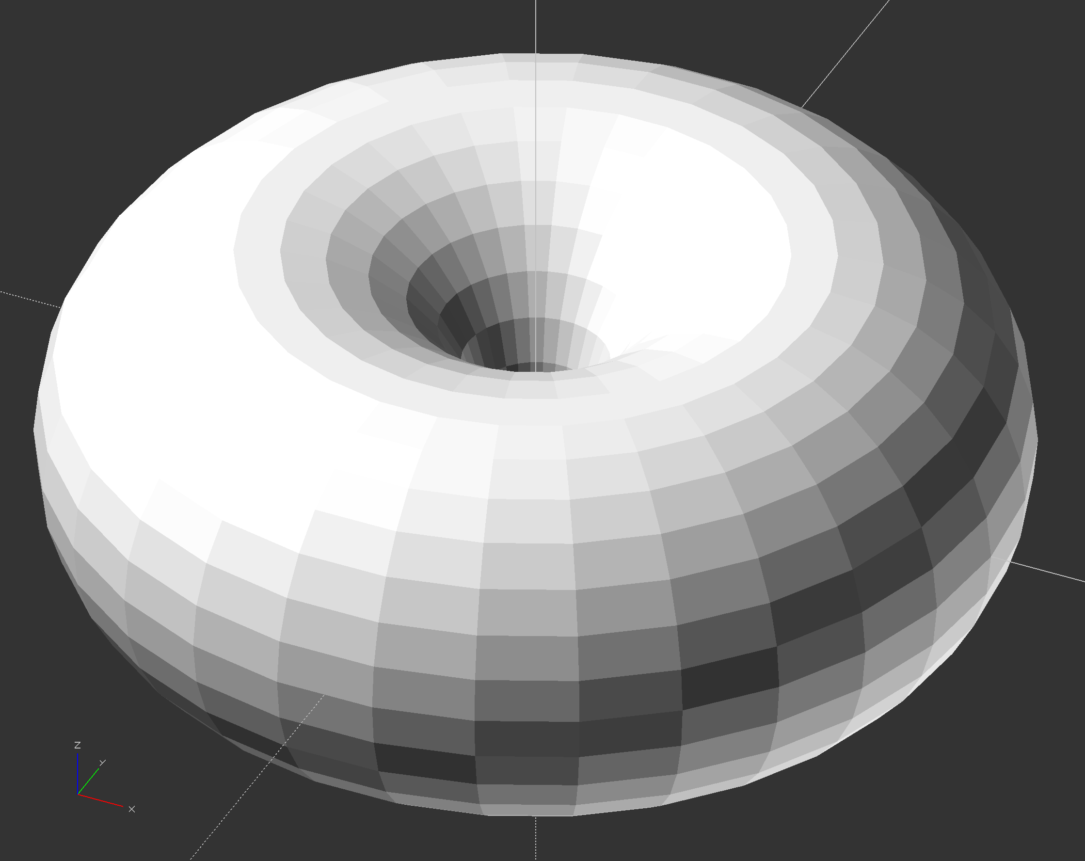
The rotate_extrude module takes a 2D shape in the x/y plane and first rotates it to the x/z plane, then it sweeps that shape around the z axis to create a 3D shape. This is useful for creating toroids (like a doughnut) and similar shapes. By default, this will sweep the shape around 360 degrees to meet up with itself, but you can optionally use the "angle" parameter to sweep the shape only part way around the axis. Note that the rotate_extrude module requires all of the 2D geometry to be in either the positive x or negative x coordinates. It will fail on geometry that crosses x = 0.
rotate_extrude() translate([25, 0, 0]) circle(20);
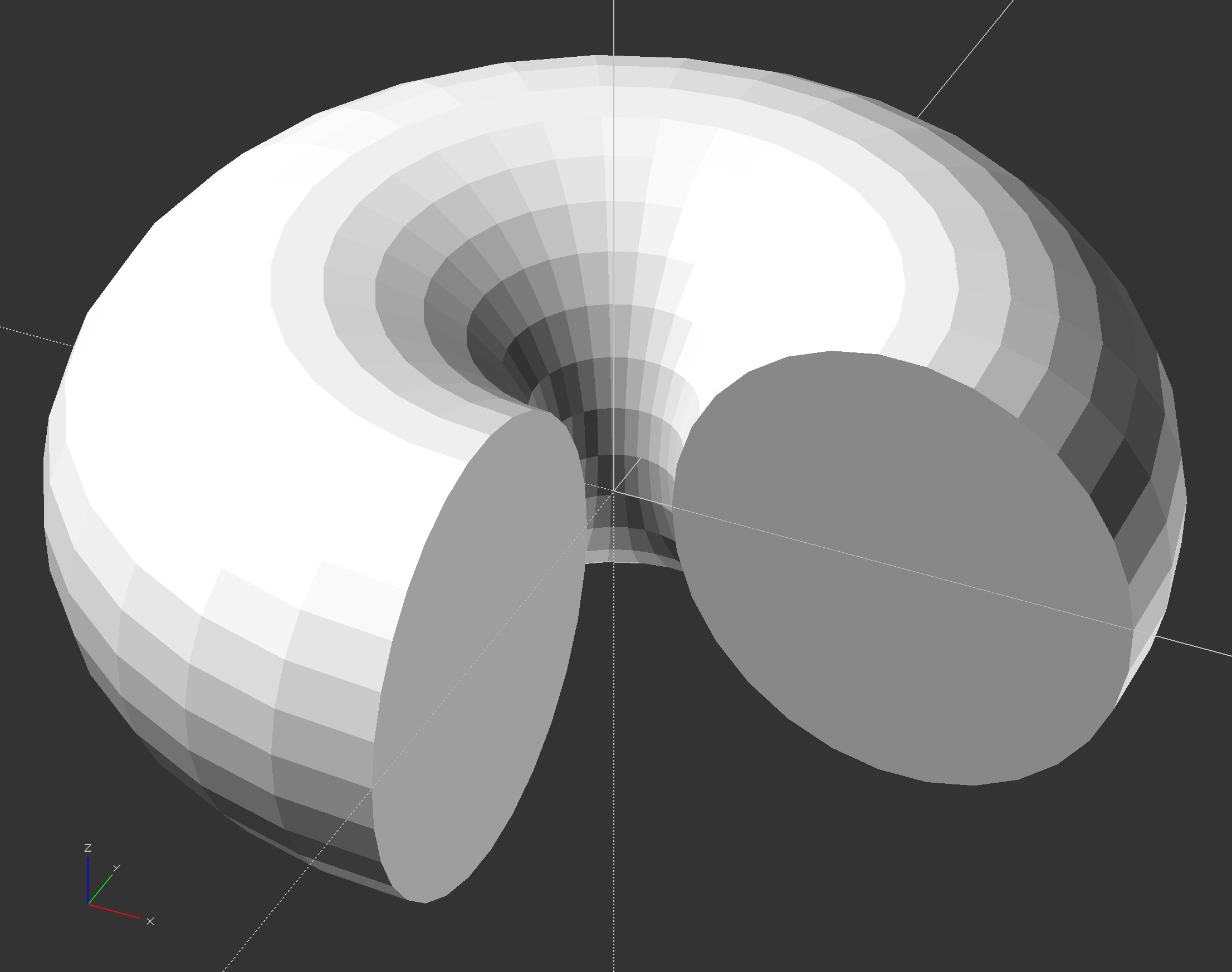
If we now introduce the angle parameter, we can just get part of our doughnut.
rotate_extrude(angle = 270) translate([25, 0, 0]) circle(20);